Importance of Circuit Breaker Maintenance
January 8, 2016 — Reliability of the power system can only happen when proper maintenance is applied to the equipment within the system. The following applies to all classes of circuit breakers from molded case thermal breakers to 765kV SF6 Gas breakers. Maintenance consists of visual inspection of the mechanical operation plus electrical tests to verify the insulation integrity and operation of the breaker. The importance of circuit breaker maintenance cannot be overstated. Circuit breakers that fail to trip properly during a faulted condition can cause fires, equipment damage and increased Arc Flash Hazards to workers performing electrical maintenance or operations. This maintenance includes the testing of the insulation medium to verify that it has the proper qualities required to dielectric protection and heat transfer abilities. Electrical tests consist of the insulation resistance test, contact resistance test, over-potential (hi-pot) test, and circuit breaker timing test.
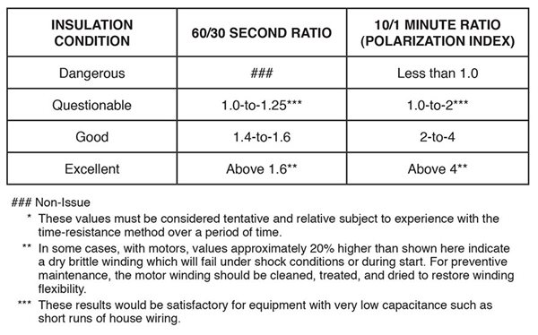
AVO Training Institute provides a complete curriculum for the testing and maintenance of an array of power circuit breakers from molded case to SF6 Gas Breakers. Our certification courses ensure technicians are applying the latest in Industry Standards and Practices for maintenance of circuit breakers. The tests outlined below briefly describe the type of tests performed on power circuit breakers and the importance of these tests as they apply to worker and equipment safety. Insulation Resistance Tests When running the insulation resistance tests, we must also take a temperature reading to apply a temperature correction because resistance is very temperature sensitive. We must apply the proper voltage to the insulation based upon the voltage class of the equipment. When reading the insulation we take readings at 30 seconds, 1 minute and if the equipment has a winding (such as a motor or transformer), at 10 minutes. We will then calculate a Dielectric Absorption Ratio. This is the reading taken at 1 minute divided by the reading taken at 30 seconds. IF a 10 minute reading is taken of a winding, we will divide the 10 minute reading by the 1 minute reading. This will give us the Polarization Index. Once the readings are taken and the calculations are made, we can use the results to grade the insulation.
Contact Resistance Tests
An important part of circuit breaker maintenance is the conductivity of the current path. For this we apply a device called a MICRO-OHMMETER or DLRO, which stands for a Digital Low Resistance Ohmmeter. Some breaker manufacturers require that a 100 Amp DLRO be used.
With this instrument we actually measure the resistance of the current path. When the DLRO is applied to the breaker line and load terminals, (with the breaker closed) we measure the current path. After all three Phases are measured, we compare the results.
In other words we compare all three phases. We will apply the 150% Rule. Our highest reading cannot exceed our lowest reading by more than 150%. If it does then we have a problem that must be corrected.
The above rule is based upon the manufacturer’s requirements for that breaker. This value could be as low as 30 microhms for some to as high as 2,000 microhms for older oil circuity breakers.
There can be any number of places in the conductive path that could be the problem. We can use the DLRO to locate the problem area.
This could be:
- Contacts
- Pivot points
- Disconnects
- Or any bolted connection
Depending upon the size and voltage class of the breaker there may be other test that can be performed on the breaker.
Over-potential test (HI POT)
Over potential tests are performed on the breaker in the same fashion as the insulation resistance tests. These tests are more likely to be used on medium and high voltage breakers.
A critical test using Over-potential is it must be used to test the bottles of a Vacuum circuit breaker for Vacuum bottle integrity. High voltage is applied across the open contact of the bottle to verify the vacuum integrity of the bottle. If this isn’t done we have no way of knowing that the bottle still has a vacuum.
Some breaker manufacturer’s require an AC hipot be used others don’t. The tester must be aware that in the event of an arc inside the bottle during the test that X-Ray radiation can be produced. As long as there is a minimum of 3 feet of distance or a piece of metal between themselves and the bottle they are safe. We are talking about minimal radiation but you must be aware of it.
Timing of the Circuit Breaker
We time a circuit breaker to verify that it performs within the manufacturers specifications. When we discuss the timing of the breaker we must talk about in two respects Low Voltage and High Voltage.
We time a Low Voltage Circuit Breaker using either a Secondary Injection Test Set or a Primary Injection Test Set.
Using the secondary injection set we apply a current (simulating the sensor or CT output) to the current input terminals of the overcurrent device on the breaker. We verify the time by using the correct characteristic curve for the breaker/overcurrent combination. Every overcurrent device has its own characteristic curve.
We will test Long Time (overload condition), Short Time (Arcing Fault), Instantaneous (Bolted Fault) and Ground Fault (self explanatory).
Using Secondary Injection we verify Pickup, Trip times, function of the overcurrent device and the trip coil.
Primary injection pushes current through the entire current path to trip the circuit breaker. The primary injection tests the same functions as with secondary injection, the difference is that in this case we will be using high current through the entire current path.
Timing in association with medium and high voltage circuit breakers is done for the same reason as the low voltage breakers but with different equipment being used.
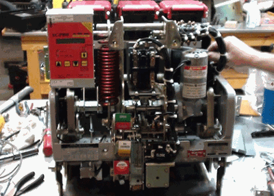
A circuit breaker travel analyzer is use to perform the travel of the main current carrying contacts.
The way the travel analyzer works follows.
With the breaker closed a signal is sent to the trip coil to activate said coil. At the same time a signal is sent to the analyzer to start it recording. The trip coil is activated, knocking the mechanical prop out from under the latch. With the mechanical prop moved it is no longer holding the breaker closed. Now gravity and the trip springs are pulling the contacts open.
The travel analyzer is connected to the linkage of the breaker with a device called a transducer. The transducer moves with the linkage and sends a signal to the analyzer. The signal starts as soon as trip signal is applied to start the timing and timing is obtained from the time the trip signal is started until the contacts part. The signal that is received from the transducer is sent to the analyzer and displayed as the movement of the contacts.
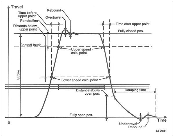
A travel trace is drawn showing the movement of the linkage. With this trace we can measure overall travel of the contacts to get:
-
- Contact opening speed.
- Total distance of contact travel.
- See any type of binding to the linkage affecting travel or opening speed.
- Any contact bounce at the end of the opening stroke indicating problems with the dashpot. (A device like a shock absorber to slow the linkage down at the end of the opening stroke.)
If we monitor all three phases we can also check the synchronization of the contacts. In other words, are all three phases operating at the same time. There should be less that .1 cycles of difference.
A travel analysis trace is shown below.
Maintenance costs
One of the major reasons to perform circuit breaker maintenance is to save money over a long period of time. One failure can cost many times more than the cost of normal maintenance and with much less down time.
Circuit breakers that have had normal maintenance performed are less likely to fail. If the breaker is less likely to fail then the danger to personnel and surrounding equipment is less likely to happen. Also a fault downstream of the breaker will be isolated quicker, generating less damage.
Power System Coordination
Protective device coordination is to ensure that all of the protective devices (relays, circuit breakers, and fuses) operate in the proper sequence during a fault situation. In other words we don’t want a feeder circuit operating incorrectly taking the main out. (This is a more common happening than we would like for it to be.)
We can have everything set properly but if maintenance has not been performed on the equipment then we really don’t know what will happen during a fault condition.
ARC FLASH Analysis
An Arc Flash Analysis is performed to determine the correct approach boundaries and the correct PPE for our protection.
The same information used for coordination studies is required for ARC FLASH Analysis.
If our equipment does not work correctly then we have wasted the money spent for the ARC FLASH Study.
If we make sure that the equipment works as it should, and we have our protective scheme set up correctly, then our system will be cost effective and as safe as humanly possible.